
I’m currently getting my home studio more organised, and along the way I’m sharing my thought process, decisions, discoveries and regrets.
I think I’ve finally figured out how I’m going to use the Neutrik NYS-SPP-L1 patchbay that I bought from Thomann for my studio rack.
I hope it makes sense to someone 🙂
What Is It?
The Neutrik NYS-SPP-L1 is a TRS patchbay for a studio rack. If you’re new to patchbays (I was!), LedgerNote has a great article about what they are and how to use them.
What’s Unique About It?
Unlike other patchbays, there are no external switches on the Neutrik NYS-SPP-L1. If you want to change how each jack pair is configured, you have to open it up and physically turn the PCBs around.
It’s a pain for sure, but not a huge deal. [This statement will not age well – Ed]
You probably will need to do this a couple of times, as you get your head around both the patchbay and your studio setup.
How Does Each Jack Pair Work?
Each PCB has four jacks on it: A and B for the back panel, and A and B for the front panel. These cards work in “half-normalled mode” by default.
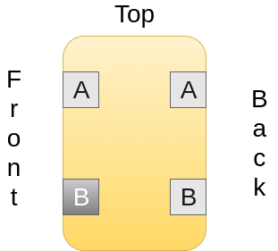
In “half-normalled mode”, you plug a signal source into the A jack on the back. The signal automatically comes out of the B jack on the back, without you having to plug anything into the front two jacks.
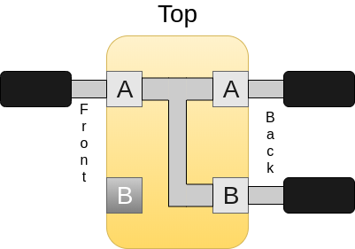
If you plug a cable into the A jack on the front, the signal is now split: it comes out of both the A jack on the front and the B jack on the back. This allows you to run the split signal to a second stack of gear of some kind. (I haven’t found a use for this myself yet).
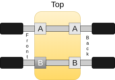
Now … plug a cable into the B jack on the front, and the PCB changes behaviour. It automatically switches over to “isolated mode”. You still plug your signal source into the A jack on the back, only now the signal only comes out of the A jack on the front. The signal no longer goes to the B jack on the back. If you want to do that, you will need to plug a signal source into the B jack on the front.
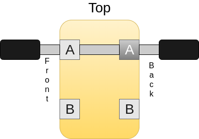
So There’s This Magic Jack?
Yes. If you plug a cable into it, the signal path changes from the split-signal to fully isolated.
From the factory, the magic jack is the bottom jack on the front of the unit. If you prefer, you can take the patchbay apart and rotate a single jack pair so that the magic jack is the top jack on the back of the unit.
That way, the jack pair operates in isolate mode by default.
How Does That Help?
I’m not looking to use my patchbay exactly how it’s done in a professional recording studio.
From what I’ve read, professional studios setup a default signal path, and then (mainly) use patchbays as a way to insert additional outboard gear into that default signal path. This works well for studios, because they’re not limited by the number of inputs into their console. They can have a large number of default routes.
That approach doesn’t work for my setup atm.
- I don’t have outboard gear to insert into the default signal path, and
- I don’t have a sensible default signal path in the first place
I’ve got a collection of signal sources – amps, the Kemper, and microphones – that need routing into my audio interface. I want to be able to route them through my pedal board, and optionally through a second pedal board that has my delay and reverb pedals on it. And I’m constrained by the number of inputs on my audio interface.
So I’m going to be using the patchbay more like an old-fashioned analogue telephone exchange, with the route defined entirely by where the patch cables are plugged in.
Setting Up The Patchbay PCBs
To make the Neutrik work the way that I want, I need to make sure that there’s (almost) always a cable plugged into the magic jack on each PCB. That guarantees a (sonically) isolated signal path for my session.
- If there’s going to be a cable plugged into the A jack on the back, that needs to be the magic jack
- and if there’s going to be a cable plugged into the B jack on the back, then the B jack on the front needs to be the magic jack.
Wait, what?
Ideally, we’d make the B jack on the back be the magic jack, but unfortunately that isn’t physically possible.
I’ve got my Neutrik open on the bench beside me.
There isn’t the physical clearance inside the unit to turn the PCB around to put the magic jack as the B jack on the back. We’re stuck with just the two options:
- B jack on the front is the magic jack (this is the default from the factory),
- or turn the PCB around to make the A jack on the back be the magic jack
That’s okay.
If there’s a cable plugged into the B jack on the back, we’re going to need to route a signal source to it. We’re going to need to plug a cable into the B jack on the front. And, because the B jack on the front is the magic jack, voila – (sonically) isolated signal path.
It’s Essential To Plan
I can’t put the Neutrik back into the rack until I’ve worked out which PCB cards need turning around. I need to make a plan:
- a list of all outputs from my gear – instrument and line level. These will get cabled into the A jacks on the back
- a list of all inputs to my gear – again, instrument and line level. These will get cabled into the B jacks on the back
- work out if any outputs should flow into any inputs by default. These will get cabled into the same jack pair
Once that’s done, I can make a start on getting everything wired in.
One Reply to “Studio Diary #7: Getting The Most Out Of The Neutrik NYS-SPP-L1”